How Camera Registration Actually Works: From a Printed Dot to Servo Movement
Teardown A1. What really happens between the moment a sheet lands on the table and the moment the servos move — pixels, template matching, contrast, and the pixel-to-millimeter bridge.
Most modern screen printing presses register their colors with a vision system: a camera finds a printed mark, and the table moves until the mark sits exactly where it should. We use this every day. But how does it actually work? In this note I take the vision chain apart step by step, in the order I learned it — starting from the very first mental picture.
The Whole Chain First
Before the details, here is the complete loop, end to end:
- Teach (once): you drag a box around the register mark and save it. What you saved is a — a small block of brightness numbers. The machine also records where the mark is right now: that becomes the target position.
- Every new sheet: the camera takes a picture. The software slides the template across the and computes a similarity at every position.
- The highest score wins. That position is the mark’s new position.
- New position − target position = offset, in pixels.
- Pixels × millimeters-per-pixel = a real distance. This goes to the servo motors, and the table moves.
- The camera takes another picture to verify. If the remaining error is within tolerance, printing starts. If not, the loop runs again.
Six steps. Every “camera problem” I have ever chased on the floor lives in one of these six steps — and most of them are really physics problems in steps 1–3.
A Camera Never Sees a Circle
This was the biggest mental shift for me, so let me be blunt: a camera does not see a dot.
The mark’s image goes through the lens and lands on a sensor. But the sensor has no idea it is looking at an image. It is a dense grid of tiny cells — a “5 megapixel” sensor is literally five million cells — and each cell does exactly one thing: report one number, how bright it is, from 0 (pure black) to 255 (pure white). Everything in between is a gray.
So the camera’s output is not a picture at all. It is a giant spreadsheet of numbers, row by row, column by column.
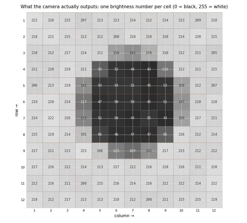
You can verify this with your phone in two minutes: photograph a printed dot, then pinch-zoom until the image turns into blocky squares. Those squares are the cells. The dot’s smooth edge becomes a staircase of gray blocks. That staircase is the machine’s whole reality.
And here is what that “grid of cells” actually looks like in hardware, zooming in from the camera itself down to a single pixel:
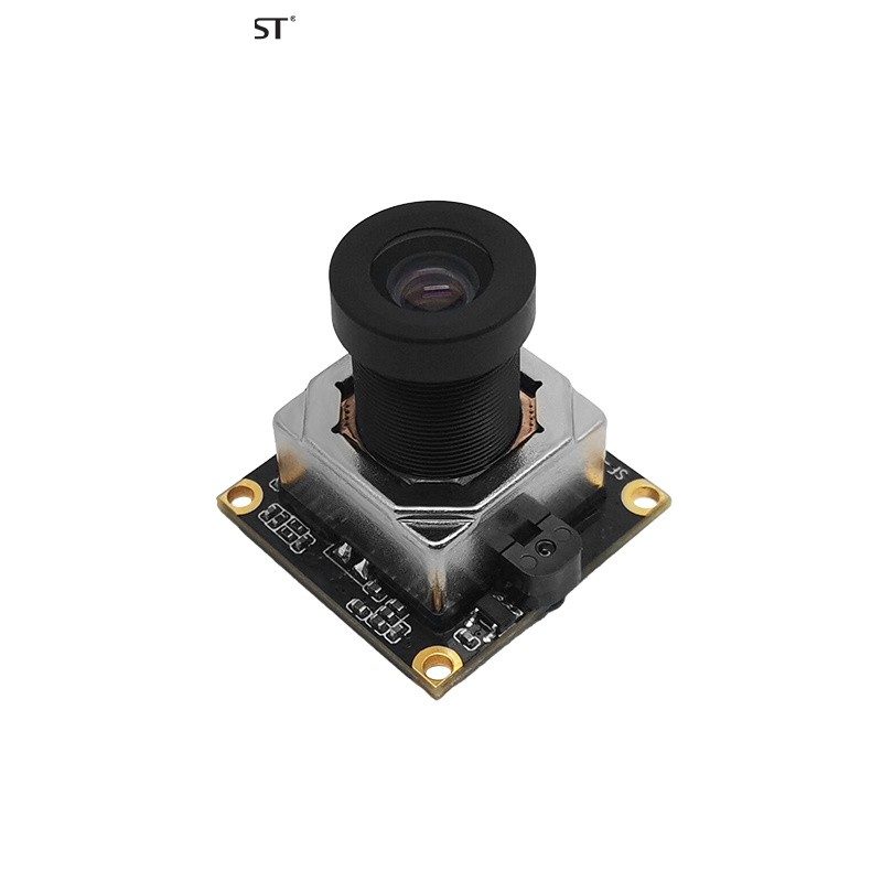
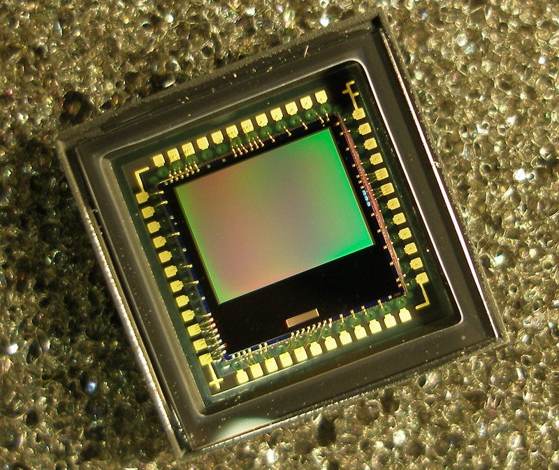
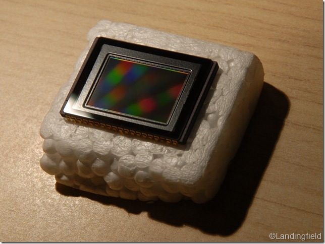
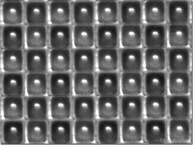
Photos above are sourced from the web for educational illustration only. If any of them infringes your rights, please contact me and I will remove it promptly.
Photo 4 is the one to remember. Those little wells are the “spreadsheet cells” this whole note is about — the number grid is not a metaphor, it is a physical object you can photograph.
Template Matching: Box It, Save It, Slide It
Registration on the machine works like this. First you pick a mark — say a solid black dot — and drag a box around it and save. From that moment, that patch of pattern is your template: a small block of numbers cut out of the big spreadsheet.
During alignment, the software takes that template and slides it across the search area of the new photo, one position at a time, computing a score at each stop. If the score at some position is very high — 0.95, 0.99 — the pattern there matches the template: registration found. If the best score anywhere is low, nothing in the search area looks like the template: the mark was not found.
The standard scoring method is called normalized cross-correlation (). Two of its properties matter on the shop floor:
- “Normalized” means it compares shape, not absolute brightness. If the whole image gets somewhat darker or brighter, the pattern of darks and lights is unchanged, so the score survives. This is why the system tolerates ordinary lighting variation.
- The winning score must beat every other position decisively. When the gap between first place and second place shrinks, the machine is hesitating — and it is close to throwing “mark not recognized.”
Why contrast is non-negotiable
Remember: the software only ever sees numbers. If mark and background are nearly the same gray, the numbers inside your template are nearly flat — and a flat template matches every flat region. There is nothing to distinguish the mark from its surroundings, so scores come out low and undecided everywhere.
Contrast is not cosmetic. Strong dark-on-light difference is what makes the correct position’s score stand far above all the wrong positions. This is also why a dark mesh needs a light backing behind the mark: you are not helping the camera “see better,” you are manufacturing the number differences the algorithm feeds on.
The Afternoon Mystery, Solved
We had a real fault: alignment ran fine in the morning, threw intermittent “mark not recognized” errors after lunch, and was fine again the next morning. No parameter had changed.
The answer was the sun. Afternoon sunlight slants through the workshop windows onto the mark area. Direct glare does something worse than “making the image brighter”: it compresses the dark-to-bright range and clips the highlights. The number difference between mark and background physically shrinks — information is destroyed, not just shifted. The score at the correct position falls toward the noise floor, and dirt specks start scoring almost as well as the real mark.
The diagnostic lesson generalizes: if a fault has a daily rhythm, look for something that changes with the time of day (sunlight, temperature, mains voltage under factory load). If it has no rhythm, look for something fixed in place (dirt on the lens, a loose bracket). Our fix was shading the window, not tweaking parameters.
From Pixels to Millimeters
“Mark found at column 350, row 240” means nothing to a servo motor. Somewhere in the system there is a conversion factor: one pixel equals a certain number of millimeters, set by the lens height and sensor resolution. With a 40 mm field of view across 640 pixels, one pixel is 0.0625 mm. An offset of 30 pixels is then a real, physical 1.875 mm that the table must travel.
That factor is not taken from drawings — a camera bolted on by hand is always slightly crooked — so the machine measures it for itself during a calibration routine. That routine is the subject of a later vision note (A4).
Sub-Pixel: Finer Than One Pixel
If one pixel is 0.0625 mm, you would expect that to be the resolution limit. It is not — and this is the part that took me the longest to understand, so here is a picture.
A mark’s edge almost never lands exactly on a cell boundary. It falls across two or three cells, so those cells report a gradient of grays instead of a clean black-white step. The software fits a curve to that gradient and locates the edge at a fraction of a pixel — a tenth of a pixel, and with good algorithms even finer.
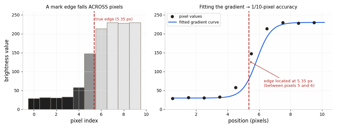
It is the same trick as reading a bathroom scale whose needle sits between two marks: the needle’s position carries finer information than the printed scale does. The gray values between black and white are the extra information. This is the mathematical root of why camera alignment beats any mechanical pin.
Try It Yourself: The Template Matching Playground
Everything above is running in the interactive playground below — the same teach → search → score loop, on a simulated (or your own photographed) mark:
- In ①, drag a box around the dark dot to teach the template.
- In ②, walk the probe with arrow keys and watch the score change with position.
- Click Score whole map and study the heat map in ③ — the reddest cell is where the machine believes the mark is.
- Crank up Ambient light = the afternoon sun arrives. Score again and watch the margin collapse.
- Drop Contrast = dark mesh without a white backing. Score again.
The terms in this article marked are live: click one and the playground scrolls to the panel where that concept is happening.
Terms in This Note
- Pixel — one cell of the sensor grid; reports a single brightness number from 0 (black) to 255 (white).
- Template — the small number block saved at teach time; the pattern the software searches for.
- Search area — the region of the new image the template is slid across.
- Probe — the playground’s test position: the score is computed as if the template sat exactly here.
- NCC score — normalized cross-correlation: the 0–1 similarity score, insensitive to uniform brightness changes.
- Score map — the score at every possible template position, drawn as a heat map.
- Contrast — the brightness difference between mark and background; the raw material of every score.
- Millimeters-per-pixel — the conversion factor that turns a pixel offset into a physical distance for the servos.
- Sub-pixel — locating an edge to a fraction of a pixel by fitting the gray gradient across cells.
What I Now Check on the Machine
After working through this, my checklist for camera faults changed completely:
- Is the mark’s contrast still strong? (Ink and mesh changes can silently degrade it — re-teach instead of tweaking parameters.)
- Is anything shading or glaring onto the mark or lens at certain times of day?
- Is the lens clean — and does the fault have a rhythm or not?
- Only then: parameters.
Note: this series documents generic engineering principles learned from publicly available vision literature and hands-on practice, not any specific manufacturer’s product. I am not affiliated with, or endorsed by, any equipment maker.