Camera Weighting Factor: Where the Error Flows
Teardown A3. Two cameras watch two register marks, but a sheet rarely sits perfectly straight. When the two cameras disagree, which one wins? The weighting factor answers that — and once keystone distortion enters the picture, it decides who absorbs an error that can never be fully removed.
In A1 we saw that a camera can align a sheet: it finds the register mark, converts pixels into millimetres, and the controller drives the servo motors by exactly that distance. One camera, one mark, one correction.
Real production is messier. A sheet hardly ever lands on the table purely shifted — it is usually rotated a little as well. A rotation cannot be measured from a single point, so the machine uses two cameras, one at each end of the sheet. With two cameras a new question appears: when the left camera and the right camera report different errors, how much should each side move? That share is the weighting factor. This note explains what it does, with a small simulator I wrote so you can watch the error flow instead of just reading about it.
First, Two Very Different Kinds of “Off”
Before touching any settings, it pays to separate two situations that look similar on the table but are completely different in physics.
Type 1 — the sheet is fine, it just sits wrong. The operator didn’t load it perfectly square, so the whole sheet is shifted and rotated as one rigid piece. Nothing is wrong with the sheet itself. A rotation plus a translation puts it back exactly. Two cameras, one rotation axis, one translation axis — done.
Type 2 — the sheet (or screen) itself is distorted. The most common shape is the trapezoid, often called keystone distortion: one end is genuinely longer than the other, or sits lower. Connect the four actual mark positions with lines and you don’t get a rotated rectangle — you get a trapezoid:
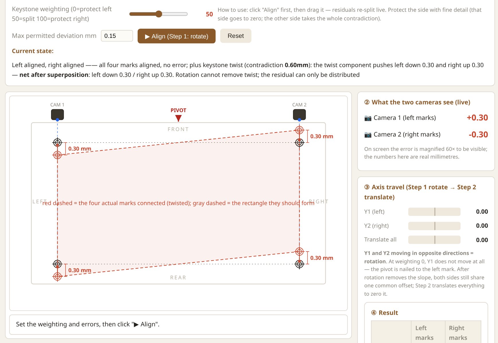
This second type matters because no rigid motion can fix it. Rotation and translation move the sheet as one stiff body; they cannot stretch one end back into line. Something will be left over no matter what you do — and where that leftover lands is exactly what the weighting factor controls.
Where does a trapezoid come from? More causes than I used to think:
- Mesh distortion — the screen mesh stretched unevenly or has aged, so the image itself is a trapezoid.
- Uneven pressure along the squeegee — if one side of the press bears harder than the other, the mesh deflects differently left vs right and the print comes out twisted.
- Uneven mesh tension from the start — the screen was tensioned unevenly at stretching time.
- Film or artwork stretch — the positive film was pulled slightly during exposure.
- Frame bow — an aluminium frame that isn’t perfectly straight.
- The sheet itself — uneven moisture or a wavy edge can make one end sit differently on the table.
Notice the pattern: some of these live in the screen, some in the artwork, some in the substrate. The machine doesn’t care — it only sees two marks that cannot both be satisfied.
Type 1 in the Simulator: Skew That Rotation Fixes
Open the simulator (embedded at the bottom of this note) and set it up: left-end error 0.00, right-end error +0.20. Black crosshair marks are where the marks should be; red ones are where the cameras actually see them. The numbers are real millimetres — the picture magnifies them 60× so your eye can follow.
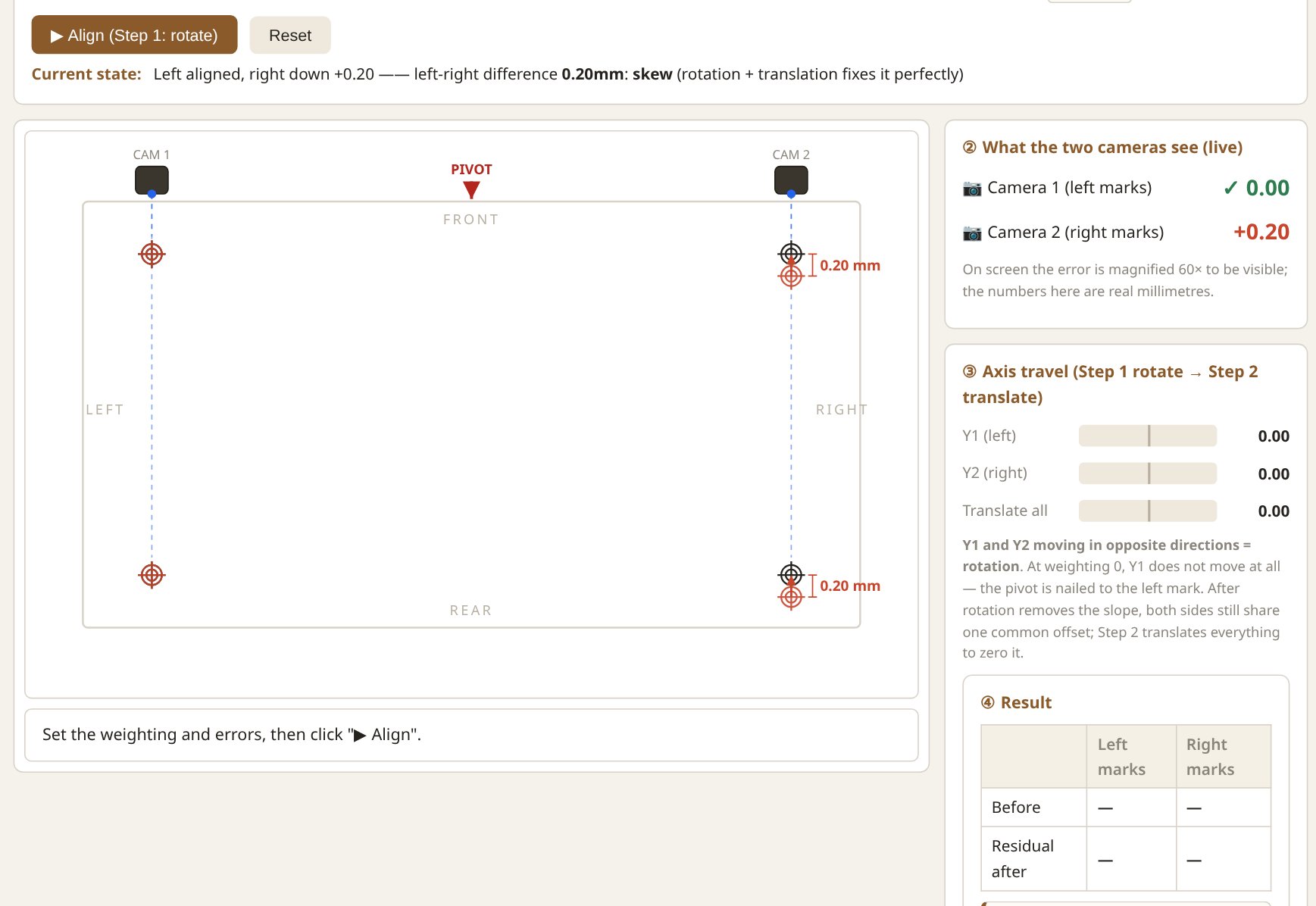
Now click Align. The animation deliberately plays in two separate steps, because that is how the physics works:
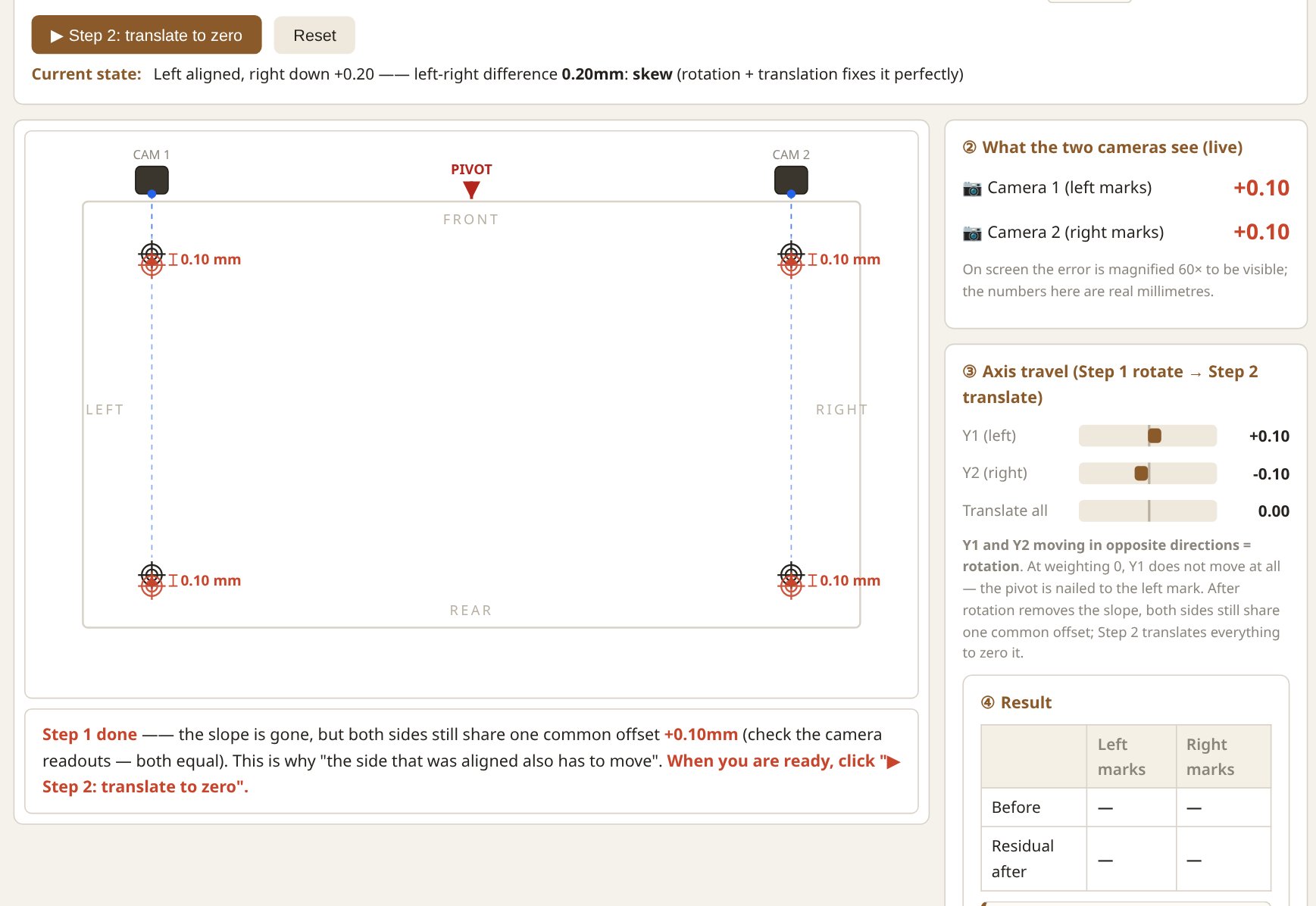
Step 1 — rotate to kill the slope. With the weighting at 50, the pivot sits in the middle: both ends move 0.10 mm in opposite directions. The sheet is now parallel to the target, but both marks still share a common offset of +0.10.
Step 2 — translate everything to zero. One shared move of −0.10 mm and both cameras read 0.00.
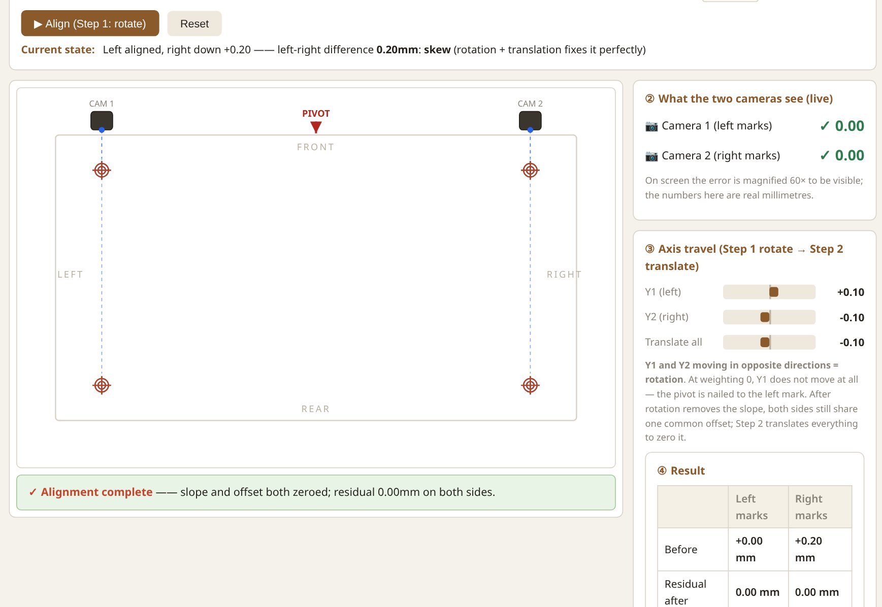
This answers a question that confused me for a while: if the left mark was already perfect, why does it move during alignment? Because rotation only removes the difference between the two ends. The common part is left over on purpose and cleaned up by the translation step. Two steps, two jobs.
What the Weighting Actually Moves
Drag the weighting slider and run the same skew again. At 0 the pivot is nailed to the left mark: the left camera never moves, the right axis (Y2) travels the full 0.20 mm. At 100 the mirror image: right side fixed, left axis (Y1) travels. At 50 they split it.
So the weighting factor is not “which camera is more accurate”. It is where the pivot sits, and therefore which axis does the travelling. On a real machine this is a practical decision: if the left end of your sheet is constrained by a guide or a gripper, you put the pivot there and let the free end move.
There is also a hard limit. Real machines refuse a correction when any single axis would have to travel more than a permitted amount. Set left −0.30, right +0.30, weighting 0, max deviation 0.15 — Y2 would need 0.60 mm, so the machine alarms and refuses:
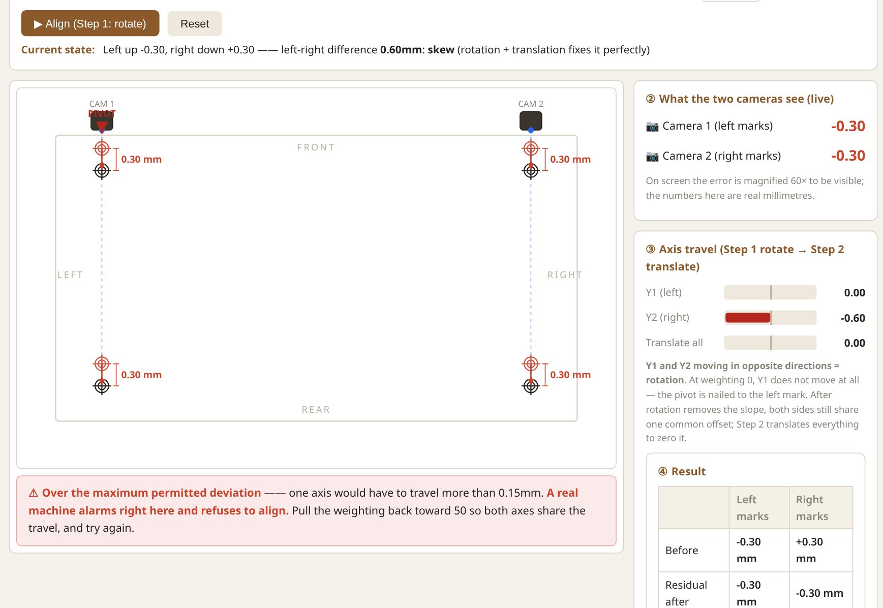
The remedy is the weighting again: share the travel between the axes and the same physical error becomes acceptable.
Type 2: Keystone, Where the Factor Becomes Real Judgment
Switch the simulator to Keystone distortion. Now both cameras start aligned (0.00), but the sheet carries a twist: the left end is pulled down 0.30, the right end pushed up 0.30. The contradiction is 0.60 mm, and here is the uncomfortable truth:
The contradiction never disappears. It only flows.
Rotation cannot remove a twist. Whatever you do, a residual stays in the print. The only choice is who carries it — and that is the keystone weighting factor:
- 50 — split it. Each end keeps half the contradiction (0.30 here). Both cameras show a small error.
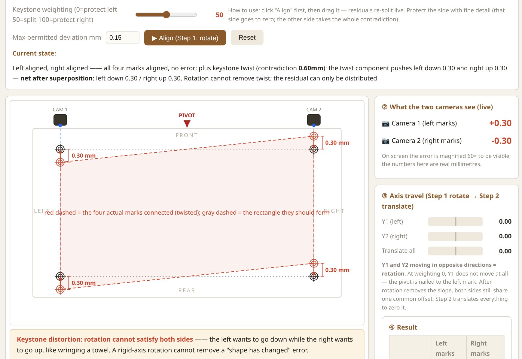
- 0 — protect the left. The left end goes to a perfect 0.00; the right end takes the whole 0.60.
- 100 — protect the right. Mirror image: right perfect, left carries everything.
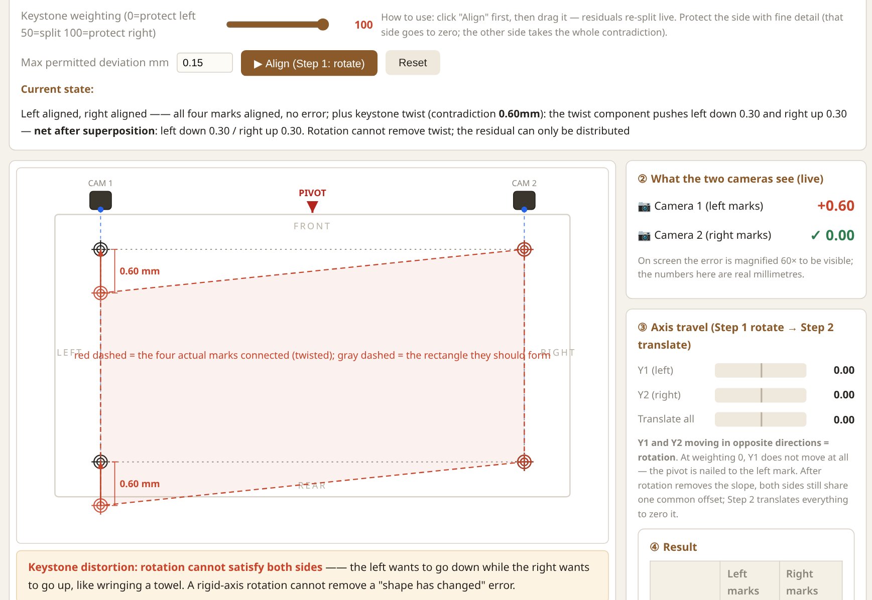
Why would you ever protect one side? Because not all errors are equally visible. If the critical part of the design — a face, a logo, fine text — sits on one end of the sheet, you nail that end and let the error collect where nobody looks. Registration is not about making everything perfect; it is about putting the imperfection where it does the least damage.
Try It Yourself
The full simulator is embedded below. Suggested path:
- Skew scenario, weighting 50 → watch the two-step align.
- Same skew, weighting 0 and 100 → watch the pivot move and the axis travel change hands.
- Push the errors past the limit → see the alarm.
- Keystone scenario → align, then drag the weighting and watch the residual flow left and right live.
The Full view button expands the tool to fill your screen.
Terms in This Note
- Weighting factor — the left/right split of a correction; effectively the pivot position of the rotation step.
- Pivot — the point that does not move during rotation. At weighting 0 it sits on the left mark; at 100 on the right.
- Skew — a rigid shift plus rotation of the whole sheet; fully correctable.
- Keystone distortion — a trapezoid deformation of the image or sheet itself; not correctable by rigid motion, only distributable.
- Contradiction — the left-right mismatch in keystone distortion that no alignment can remove; it can only be assigned to one end or shared.
- Residual — the error left in the print after alignment. In keystone jobs the residual is a choice, not a failure.
- Axis travel limit — the maximum distance one servo axis may move in a single correction; exceeding it triggers an alarm instead of an align.
In A4 we leave the camera alone and look at the marks themselves: what makes a good register mark, and why some shapes teach better than others.